Case 1 direct pull: 28.6 N (thick flat steel)Case 2 sandwich pull: 16.00 lbf (71.2 N)
Single magnet weight
3.057 g
Batch weight
3.06 kg
Aspect ratio (t/D)
0.250
Est. surface field
~2,952 Gauss
Volume
0.4022 cm³
Weight assumes sintered NdFeB density of 7.6 g/cm³. A pull value, when available, is a published reference for a 1/2 in diameter stock disc on thick, flat steel with no separate gap. It does not predict the selected contact condition or validate an assembly; request a representative test. Surface field assumes an isolated, uniformly axially magnetized cylinder at room temperature: Br is 11,950/13,200/13,500/14,000/14,800 G for N35/N42/N45/N48/N52. Nearby steel, probe offset and material variation change the field; it is not a pull-force prediction. Pc and thermal limits require a circuit model and grade-specific B-H curves. The 1/4 in N52 comparison is K&J D84B-N52 with black nickel coating; these supplier results are not our product guarantees or safe working loads.K&J reference specifications (checked 2026-11-10)
1. Four decisions before choosing a disc
Reference check: . Calculations, supplier comparisons and unknown assembly performance are identified separately under MMPA Standard 0100-00 and IEC 60404-8-1.
Geometry
12.7 × 3.175 / 6.35 mm
Exact nominal conversion; aspect ratio t/D = 0.250 (1/8") and 0.500 (1/4"). Open-circuit permeance is Pc ≈ 0.31 for 1/8" vs Pc ≈ 0.61 for 1/4". Flexural rigidity scales as t³, giving 1/8" discs 8× greater bending resistance than 1/16".
Planning mass
3.057 g / 6.113 g
Calculated from 0.4022 cm³ (1/8") and 0.8044 cm³ (1/4") at standard sintered NdFeB density 7.60 g/cm³ (range 7.50–7.60 g/cm³ per MMPA). 1,000 pcs of 1/8": 3.057 kg net magnet mass.
Catalog Case 1
6.44 / 10.88 lbf
N42 D82 (1/8", 28.6 N) / D84 (1/4", 48.4 N) supplier comparisons against thick mild steel. In N52, pull reaches 7.97 lbf (D82-N52) and 13.47 lbf (D84B-N52). D82 · D84
Assembly capacity
Test required
Case 2 sandwich pull reaches 16.00 lbf (N42) and 19.81 lbf (N52) for 1/8" (2.48× Case 1 multiplier). Normal pull does not predict lateral shear resistance (μ ≈ 0.18 yields ~1.16 lbf). Test definitions
2. Nominal dimensions and a fit method
1/2" × 1/8" target (D82). Nominal cylinder; coating and edge breaks omitted.1/2" × 1/4" target (D84). Nominal cylinder; coating and edge breaks omitted.1/2" × 1/16" thin alternative (D81). Nominal cylinder; coating and edge breaks omitted.
Exact inch conversions and mechanical baseline per MMPA 0100-00; no production tolerance is implied
Parameter
1/8 inch thick (D82)
1/4 inch thick (D84)
1/16 inch thick (D81)
Diameter
12.7000 mm
12.7000 mm
12.7000 mm
Thickness
3.1750 mm
6.3500 mm
1.5875 mm
Aspect ratio t/D
0.250
0.500
0.125
Open-circuit permeance (Pc)
≈ 0.31 (moderate load line)
≈ 0.61 (stiff load line)
≈ 0.13 (prone to thermal knee)
Volume
0.4022 cm³
0.8044 cm³
0.2011 cm³
Nominal mass (7.60 g/cm³)
3.057 g
6.113 g
1.528 g
Relative bending stiffness (∝ t³)
8.0× (good fracture resistance)
64.0× (high impact rigidity)
1.0× baseline (fragile under pinch shock)
Finished dimensional limits
Agree after coating (±0.05 mm standard)
Agree after coating (±0.05 mm standard)
Agree after coating (±0.05 mm standard)
For an adhesive pocket, first calculate minimum diametral clearance as bore minimum minus finished magnet maximum. With nominal 12.70 mm magnets ground to ±0.05 mm (12.65 to 12.75 mm OD), machine a pocket bore of 12.85 to 12.95 mm (+0.15 to +0.25 mm clearance) to ensure a uniform 0.05 to 0.10 mm glue line. For a 1/8" disc, specify pocket depth at 3.28 to 3.38 mm to accommodate adhesive wet-out and maintain flush surface alignment. Sintered NdFeB has tensile strength of only ~75–80 MPa with zero ductility (Young's modulus ~160 GPa per MMPA Standard 0100-00); never attempt a press-fit or mechanical staking, as hoop stresses will cause catastrophic fracture.
3. Compare the 1/2 inch disc family
The 1/8 inch disc (12.7 × 3.175 mm, D82) delivers 6.44 lbf (28.6 N) Case 1 pull in N42 and 7.97 lbf (35.5 N) in N52, striking a popular balance between holding power and low profile. The 1/4 inch disc doubles thickness to 6.35 mm (10.88 lbf N42 / 13.47 lbf N52), while the 1/16 inch disc provides a 1.5875 mm thin profile (3.10 lbf N42). In a Case 2 sandwich configuration (clamped between two thick steel plates), closing the magnetic circuit increases pull force on a 1/8" disc by 2.48× (from 6.44 lbf to 16.00 lbf in N42), compared to 1.49× for a 1/4" disc, because reducing open-circuit leakage has a proportionately greater impact on thinner geometry.
Third-party catalog Case 1 data. Sources and nominal masses are in the table below.
K&J catalog Case 1 comparisons, checked 2026-11-10; lbf, not working loads
The 1/4 inch N52 entry is D84B-N52, with black nickel coating. It is a comparison of actual catalog parts, not an isolated experiment on grade alone. Other N52 sizes listed here use their linked part specifications. Full source catalog.
Case 2 uses two thick steel plates; these verified values do not apply to Case 1
Thickness (in)
N42 Case 2 (lbf)
N52 Case 2 (lbf)
1/16
14.00
17.33
1/8
16.00
19.81
3/16
16.10
19.93
1/4
16.20
20.06
Case 2 values for 1/32 and 3/32 inch sizes are not included because they were not verified in this review. K&J pull-test definitions.
4. Model the field, then test the gap
The tool and table use one cylinder model, with nominal Br = 13,200 G for N42 and 14,800 G for N52. The model assumes an isolated, uniformly axially magnetized cylinder at room temperature, with no steel target. Field method and measurement location.
Calculated, not measured. Br = 13,200 G; points joined for readability. Exact sampled values appear below.
Bz(x) = Br/2 · [(x+t)/√(R²+(x+t)²) − x/√(R²+x²)], R = D/2
Calculated on-axis field (G); x is measured from the magnet face, without steel
Distance x (mm)
1/8 inch N42
1/4 inch N42
1/16 inch N42
Holding force across gap
0
2,952
4,667
1,601
Unknown: assembly test required
0.5
2,788
4,322
1,543
Unknown: assembly test required
1
2,599
3,968
1,464
Unknown: assembly test required
2
2,187
3,271
1,264
Unknown: assembly test required
3
1,782
2,641
1,046
Unknown: assembly test required
5
1,129
1,677
669
Unknown: assembly test required
10
374
581
216
Unknown: assembly test required
All values in this chart and table are calculations, not measurements. Adding steel changes the circuit. Neither the free-space field nor its square is a validated steel-attraction force model. For a Hall sensor, compare the component along its sensitive axis with the actual sensor thresholds, alignment, temperature and allowed saturation range.
5. Temperature and permeance: what remains unknown
Aspect ratio is a geometry output, not a thermal approval. This tool does not estimate Pc: a reliable operating point needs the chosen material’s temperature-dependent B-H curves and the actual circuit. For an isolated 1/8" disc in free space, Parker’s cylinder approximation gives an open-circuit permeance coefficient Pc ≈ 0.31 (compared to Pc ≈ 0.61 for 1/4" and Pc ≈ 0.13 for 1/16"). Because lower permeance shifts the operating point closer to the demagnetization knee, standard N-grades (rated for 80°C in closed circuits) may experience irreversible flux loss starting above 65°C–70°C in open circuits or when exposed to opposing demagnetizing fields. A steel return path elevates Pc, so an isolated-magnet estimate cannot certify the assembled part. Manufacturer explanation and examples.
Thermal review inputs and operating limits (MMPA Standard 0100-00 & IEC 60404-8-1)
Known or supplied input
Missing evidence
Next decision
12.7 × 3.175 mm geometry (t/D = 0.250)
Operating load line Pc ≈ 0.31; self-demagnetization margin
Model the assembled circuit to check permeance coefficient
Standard N42 / N52 rating (Tmax = 80°C)
Open-circuit knee starts at 65°C–70°C for Pc ≈ 0.31
Select N42M (100°C) or N42H (120°C) if operating above 65°C
Thermal coefficients: α(Br) ≈ -0.11%/°C
β(Hcj) ≈ -0.55%/°C; elevated temperature coercivity drops faster
Calculate maximum opposing field and minimum flux threshold
Curie temperature Tc ≈ 310°C–340°C
Post-cycle irreversible flux loss under dynamic load
Qualify actual production lot samples with hysteresis loop test
For a 95°C application, send the actual continuous and peak temperatures, exposure duration and magnetic circuit for review. Higher-coercivity grades (M, H, SH, UH, EH) maintain linear demagnetization behavior at higher temperatures; do not assign a universal safe temperature from thickness or a suffix alone.
Case 1: normal pull from one plate. The force value is specific to this configuration.Case 2: two plates change the magnetic circuit. The force value is specific to this configuration.
Target thickness, saturation and gap effects on magnetic holding circuit
Target or circuit
What changes
Minimum validation
Thick flat mild steel (≥ 6.35 mm, AISI 1018)
Direct contact; closest match to catalog Case 1 (6.44 lbf N42)
Match laboratory test ground plate specification
Thin sheet steel (e.g. 0.6–0.8 mm / 22–24 gauge)
Magnetic saturation (Bsat ≈ 1.8–2.1 T); flux leaks out back; 30–50% pull drop
Test actual alloy grade, thickness, and sheet backing
Paint, tape, adhesive, or powder coat gap
Steep non-linear force drop; even 0.2 mm coating reduces pull by ~35–45%
Measure exact circuit breakaway force; no arbitrary multiplier
No universal minimum plate thickness or percentage derating is established here. K&J’s steel-thickness study explains why target geometry belongs in the test specification.
7. Pull-off force is not lateral retention
Normal pull separates the faces; shear moves them sideways. A friction screening equation is Fshear = μ · Fnormal, where μ is the coefficient of friction and Fnormal is the normal magnetic clamping force. For smooth electroplated nickel (Ni-Cu-Ni) against ground mild steel, typical dry friction is only μ ≈ 0.15 to 0.20. Consequently, an N42 1/8" disc delivering 6.44 lbf (28.6 N) direct breakaway force provides only ~1.16 lbf (5.1 N) of lateral sliding resistance. For an N42 1/4" disc (10.88 lbf), lateral resistance is ~1.96 lbf (8.7 N).
For dynamic assemblies, vibration, or suspended loads, never rely on magnetic friction alone. Design positive mechanical retention, such as a machined pocket counterbore with a retaining lip, or apply a high-friction elastomeric polyurethane or rubber contact layer (which elevates μ to 0.5–0.8, boosting shear holding to 3–5 lbf). Ensure the pocket structure accounts for magnet brittle fracture limits (tensile strength ~75–80 MPa per MMPA 0100-00). Add secondary mechanical safety retention wherever accidental displacement poses an injury risk.
8. Coatings and environmental qualification
Standard sintered NdFeB is highly susceptible to atmospheric oxidation and intergranular corrosion due to its neodymium-rich phase at grain boundaries. Catalog parts such as D82 and D84 use standard electroplated Ni-Cu-Ni; D84B-N52 uses black nickel. Environmental durability must be qualified against standard test protocols such as ASTM B117. D82 specifications · D84 specifications.
Coating performance and environmental qualification per ASTM standards
Candidate
Decision question
Evidence required
Ni-Cu-Ni electroplating (12–15 µm total)
Will indoor humidity, condensation, or hand sweat corrode it?
ASTM B117 salt fog 24–48 h test report; cross-hatch adhesion ASTM D3359
Black Epoxy coating (15–25 µm)
Does application require chemical, moisture, or saline resistance?
ASTM B117 salt fog > 72–120 h; solvent rub testing (ASTM D5402)
Zinc plating + trivalent passivate (8–12 µm)
Is cost-effective indoor galvanic protection needed against steel?
ASTM B633 Type II qualification; 24–72 h salt spray before white rust
Parylene C vapor deposition (10–20 µm)
Is medical biocompatibility or pinhole-free hermetic sealing required?
USP Class VI certification; ISO 10993 cytotoxicity and autoclave test
Neutral salt-fog (ASTM B117), pressure cooker tests (PCT / HAST: 121°C, 2 atm, 100% RH for 48–96 hours), and cyclic humidity testing address different corrosion mechanisms. Agree test conditions, exposure duration and post-test acceptance criteria (no blistering, pitting, or flux degradation); never convert test hours directly into field lifespan. Medical and aerospace certifications require lot-specific conformance certificates.
9. Tolerances, cost and sourcing tradeoffs
Manufacturing tolerances, inspection and logistics tradeoffs (MMPA 0100-00 & IATA DGR PI 953)
Choice
Potential cost or fit effect
Practical next step
1/8" (3.175 mm) vs 1/4" (6.35 mm) thickness
1/8" uses half the raw material volume (0.402 cm³ vs 0.804 cm³), saving ~45% unit cost
Verify whether 6.44 lbf pull meets safety factor before paying for 1/4" thickness
Standard (±0.05 mm) vs Precision (±0.02 mm) grinding
Precision centerless grinding adds ~15–25% processing and sorting cost
Specify ±0.02 mm only where automated pick-and-place requires tight robotic feed
Standard N42 vs High-temp N42SH grade
Dysprosium/Terbium heavy rare-earth dopants increase raw material cost by 20–40%
Model actual magnet temperature; avoid paying for SH if application remains below 70°C
Bulk packing vs IATA PI 953 Air Transport Shielding
1,000 pcs (3.06 kg net) requires steel flux return liners to stay under 5.25 mG at 4.6 m
Include packed-carton magnetic Gauss inspection certificate in purchase order
Stock, price, MOQ, production route, inspection coverage and lead time remain subject to formal quote confirmation. The mass calculation excludes chamfers, coatings, adhesive and packaging; weigh production-run samples for exact shipping tare.
10. Assembly and handling checks
Control magnetic snap attraction with non-magnetic brass or delrin spacers and mechanical fixtures. Keep fingers clear; a chamfer does not prevent severe pinching.
Prevent uncontrolled collisions. Uncontrolled snap-together impact velocities can exceed 5–10 m/s, generating peak contact pressures far beyond the 240–260 MPa flexural strength of sintered NdFeB, shattering the magnet core and stripping the protective nickel plating.
Review adhesive surface preparation, bondline clearance (0.05 to 0.10 mm radial clearance), cure temperature, and degreasing with isopropyl alcohol (IPA) before applying structural acrylic (Loctite 326/330) or toughened epoxy (3M DP420/DP460).
Do not machine, drill, or grind a finished sintered magnet as a fit correction. Machining destroys plating, produces flammable NdFeB dust, and causes thermal demagnetization. Request finished drawing limits from the factory.
These are assembly review points, not a complete handling procedure. Follow the delivered product’s safety instructions and qualify the chosen fixture and retention method.
11. Three worked selection examples
Illustrative planning examples, not customer case histories or completed tests. Outcomes below are next decisions, not performance claims.
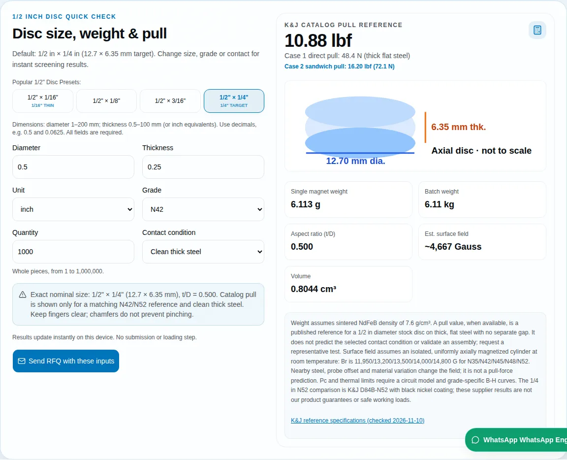
Original software execution, captured 2026-11-10. Reproduce with diameter 0.5 in, thickness 0.25 in, N42, 1,000 pieces and clean thick steel. Mass uses 7.6 g/cm³; nominal Br is 13,200 G. The capture shows catalog comparisons and modeled geometry/field, not a physical magnet test, customer case or product certification. Only the tool region is captured; site navigation is outside the image.
Cabinet latch with 1/8 in disc
Premise: A 12.7 × 3.175 mm N42 disc (D82) contacts a clean 1.5 mm mild steel strike plate.
Check: Case 1 catalog benchmark is 6.44 lbf (28.6 N). With a 0.2 mm vinyl or paint gap, pull drops to ~3.8 lbf. Mass is only 3.057 g; thickness is just 3.175 mm.
Next decision: Specify strike plate thickness, non-magnetic paint build, and minimum 3.0 lbf retention for sample latch testing.
Sensor behind a 3 mm partition
Premise: An axial N42 disc is aligned with a Hall sensor across a 3 mm non-magnetic aluminum partition.
Check: The Biot-Savart cylinder model calculates 1,784 G on axis at 3 mm for 1/8" (vs 2,431 G for 1/4"), using 13,200 G Br. For a 50 G sensor operate point, 1,784 G provides >35× operating margin.
Next decision: Check sensor saturation threshold and axis alignment; 1/8" disc provides 50% thinner profile and reduces stray field on neighboring electronics.
1,000-piece batch mass & air shipping
Premise: Plan nominal net mass and freight compliance for 1,000 pcs of 1/2 × 1/8 inch discs.
Check: 3.057 kg net magnet mass (3.057 g/ea at 7.60 g/cm³) vs 6.113 kg for 1/4". IATA PI 953 steel shielding adds ~1.2–1.5 kg package tare.
Next decision: Request carton magnetic field inspection report (<5.25 mG at 4.6 m) to clear air freight as non-restricted magnetized material.
12. Turn the result into a testable RFQ
Define geometry
Describe circuit
Agree tests
Review samples
Finished diameter, thickness, tolerances and edge requirement after coating.
Grade, axial direction, pole marking and material data required.
Target alloy, contact area, thickness and maximum total gap.
Normal and shear loads, shock, vibration and retention arrangement.
Temperature range, fluids, moisture, coating and adhesive.
Quantity, sample plan, test fixture, acceptance limits and delivery destination.
Use “Send RFQ with these inputs” in the calculator to create an email draft containing the current dimensions, grade, quantity, condition and benchmark limitations. If inputs are invalid or no pull match exists, “Ask for drawing review” gives a usable fallback template. For air freight, confirm packed-carton requirements with the carrier; no shipping classification is determined by this page.
It specifies a 1/2 inch diameter by 1/8 inch thick disc magnet: exactly 12.7 × 3.175 mm nominal (D82 catalog class). It is typically axially magnetized through its 3.175 mm thickness with flat circular poles on either face, providing an aspect ratio t/D = 0.250 and open-circuit permeance coefficient Pc ≈ 0.31.
What does “1 2 x 1 4 disc neodymium magnet” mean?
It specifies a 1/2 inch diameter by 1/4 inch thick disc magnet: exactly 12.7 × 6.35 mm nominal (D84 catalog class). It has an aspect ratio t/D = 0.500 and open-circuit permeance coefficient Pc ≈ 0.61 with flat circular poles on either face.
Can I type 1/2, 1/8 or 1/4 into the calculator?
Use a size preset or decimal inputs: 0.5 diameter and 0.125 or 0.25 thickness in inch mode. Fraction strings are rejected with recovery guidance. Changing to mm converts the current dimensions.
Is 12.7 × 1.59 mm the same as the 1/16 inch preset?
1/16 inch is exactly 1.5875 mm. A rounded 1.59 mm input still produces geometry and field estimates, but the catalog lookup requires an exact nominal match within 0.0001 mm. Use the preset to select the catalog geometry.
Force & field
How much pull does a 1/2 × 1/8 inch disc have?
K&J lists 6.44 lbf Case 1 (28.6 N) for N42 D82 and 7.97 lbf (35.5 N) for N52 D82-N52, checked 2026-11-10. In a Case 2 sandwich configuration, pull reaches 16.00 lbf (N42) and 19.81 lbf (N52). These are supplier comparisons against thick flat mild steel, not safe working loads.
How much pull does a 1/2 × 1/4 inch disc have?
K&J lists 10.88 lbf Case 1 for N42 D84 and 13.47 lbf for black-nickel N52 D84B-N52, checked 2026-11-10. These are supplier comparisons against thick flat steel, not NdFeB Shapes product ratings or safe working loads.
How strong is a 1/2 × 1/8 inch disc magnet compared to 1/2 × 1/4 inch?
In direct breakaway against thick steel (Case 1), an N42 1/2 × 1/8 inch disc (D82) provides 6.44 lbf (7.97 lbf in N52), while a 1/2 × 1/4 inch disc (D84) provides 10.88 lbf (13.47 lbf in N52). Doubling thickness increases pull by ~69%, but doubles volume and mass.
Why are Case 1 and Case 2 different?
Case 1 pulls one magnet from a thick steel plate. Case 2 separates a magnet sandwiched between two thick steel plates. For a 1/8" disc (t/D = 0.250), closing the magnetic circuit with a second plate yields a 2.48× pull multiplier (16.00 lbf vs 6.44 lbf), compared to 1.49× for a 1/4" disc. They describe different circuits and cannot be substituted for one another or for lateral shear resistance.
Can the tool predict holding force across paint or a gap?
No. Selecting paint/air gap or thin sheet suppresses both catalog force outputs. The field model describes an isolated magnet; it cannot predict attraction to steel. Test the complete assembly with its actual coating, gap, target, and load direction.
What does the Gauss result mean?
It is a model estimate at the center of an isolated, uniformly axially magnetized cylinder face, using the stated nominal Br. It is not a pull force, a whole-face average, or a guaranteed Hall sensor reading. Probe offset, alignment, temperature and nearby steel change the result.
Thermal & assembly
Does thicker geometry guarantee a safe operating temperature?
No. Geometry affects the load line (Pc ≈ 0.31 for 1/8" vs Pc ≈ 0.61 for 1/4"), but the material B-H curves, circuit, opposing fields and temperature determine irreversible loss. This tool does not calculate Pc or certify a temperature limit. Send the actual thermal envelope for grade review.
Can I use a standard N42 or N52 disc at 100°C?
Do not approve it from a general grade label. Standard N-grades are rated up to 80°C in closed circuit, but in open circuit (Pc ≈ 0.31 for 1/8"), irreversible demagnetization can initiate above 65°C–70°C. For 100°C service, specify M, H, or SH grades (such as N42H or N42SH with Hcj ≥ 17–20 kOe). Request grade-specific temperature curves and validate the assembled magnet after heating and cooling.
What pocket dimensions should I machine?
Agree finished magnet limits, coating thickness, housing limits, adhesive bondline and temperature range first. A nominal 12.7 mm disc carries ±0.05 mm standard tolerance. For an adhesive slip fit, machine a bore of 12.85 to 12.95 mm (+0.15 to +0.25 mm clearance) and depth of 3.28 to 3.38 mm (for 1/8" disc) to provide a 0.05–0.10 mm glue line. Sintered NdFeB has tensile strength of only ~75–80 MPa with zero ductility; never press-fit into an undersized metal pocket.
Sourcing
Does epoxy or nickel coating guarantee corrosion life?
No. Coating name alone does not establish thickness, porosity, adhesion or durability. Standard Ni-Cu-Ni (12–15 µm) passes 24–48 h salt fog (ASTM B117), whereas double epoxy (15–25 µm) offers superior chemical and moisture resistance (>72–120 h). Specify the service environment, test method, duration and failure criteria, then request evidence for the actual coating and production lot.
How are weight, price and shipment readiness established?
Weight here is nominal cylinder volume times an assumed 7.6 g/cm³ density (3.057 g/pc for 1/8", 6.113 g/pc for 1/4"); packaging is excluded. Air shipment compliance requires carton magnetic shielding under IATA DGR Packing Instruction 953 (compass deflection < 0.00525 G at 4.6 m). Price, MOQ, lead time, certificates and air shipment acceptance require a written quote and packed-carton testing. The calculator makes no stock or dispatch promise.
14. Sources and limits of this guide
Published by NdFeB Shapes; technical content review is scheduled every six months, or sooner if the linked specifications change. Sources checked 2026-11-10. Catalog figures describe the linked supplier parts under its test conditions. Standard magnetic and mechanical properties follow international standards for sintered rare-earth permanent magnets.
MMPA Standard 0100-00: Standard specifications for permanent magnet materials (physical, mechanical and magnetic properties of sintered NdFeB).
IEC 60404-8-1: International standard specifications for magnetically hard materials.
ASTM A977 / A977M: Standard test method for magnetic properties of high-coercivity permanent magnets using hysteresigraphs.
ASTM B117: Standard practice for operating salt spray (fog) apparatus for coating corrosion qualification.
IATA DGR Packing Instruction 953: Magnetized material regulations (UN 2807) for air cargo shielding and compass deflection limits.
K&J Magnet Finder: Case 1 comparisons for the 1/2 inch family; individual part links are in the tables.
D82 N42 and D82-N52: 1/2 × 1/8 inch target dimensions and Case 1 / Case 2 pull benchmarks.