
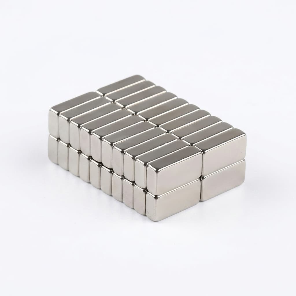
Evaluating NdFeB Coating Reliability: A Buyer's Guide to SST, PCT, and Edge Chamfering
Specify custom NdFeB magnet coatings with SST, PCT, and chamfer checks. Use this buyer guide to reduce corrosion risk before RFQ.
For procurement teams and lead engineers sourcing custom NdFeB magnet product families for motors, sensors, and renewable energy applications, corrosion remains the single most common cause of catastrophic field failures. Unlike other magnetic materials such as Ferrite or Alnico, NdFeB is highly reactive. Without a properly applied and tested protective layer, a Neodymium magnet will oxidize rapidly, leading to swelling, structural crumbling, and a permanent loss of magnetic flux.
However, merely specifying "Ni-Cu-Ni coating" on a 2D drawing is no longer sufficient for modern, high-reliability applications. In 2026, navigating the complexities of magnet surface protection requires a deep understanding of environmental stress testing—specifically the Salt Spray Test (SST) and the Pressure Cooker Test (PCT)—as well as the mechanical prerequisites for successful electroplating, such as edge chamfering.
This comprehensive guide is designed to help buyers, supply chain managers, and engineers evaluate NdFeB coating reliability. It breaks down the differences between coating tests and substrate tests, provides a detailed comparison matrix of available surface treatments, explains the critical physics of edge effects, and equips you with an actionable RFQ checklist to ensure your suppliers deliver defect-free magnets.
Updated July 18, 2026. Scope and limits: This guide applies to sintered custom NdFeB magnets used in industrial OEM assemblies. It is not a substitute for a project-specific qualification plan, medical regulatory review, or automotive PPAP sign-off. Treat the hours and thicknesses below as procurement screening targets, then confirm them with supplier test reports, sample inspection, and application-level validation.
If your drawing is still missing coating stack, magnetization direction, or acceptance criteria, pair this guide with the magnetization and coating RFQ guide before releasing the inquiry.
1. Why NdFeB Magnets Corrode
Before evaluating coatings and testing standards, it is crucial to understand why Neodymium magnets are so vulnerable to corrosion. The inherent chemical instability of sintered NdFeB magnets stems from their microstructure.
A sintered NdFeB magnet consists of primary grains of the Nd2Fe14B magnetic phase, surrounded by a Neodymium-rich grain boundary phase. This Nd-rich grain boundary is electrochemically active and highly anodic compared to the primary magnetic phase. When exposed to moisture (even high ambient humidity), a galvanic cell is formed between the Nd-rich grain boundary and the Nd2Fe14B grains.
The resulting intergranular corrosion attacks the grain boundaries first, effectively dissolving the "glue" that holds the magnetic crystals together. As the oxidation byproducts take up more volume than the original metal, the magnet begins to swell from the inside out. This internal expansion causes the protective coating to blister and eventually crack, accelerating the degradation process until the magnet mechanically crumbles into magnetic dust.
Because this corrosion propagates internally, by the time rust is visible on the surface of the magnet, the internal structural integrity and magnetic performance have already been irreversibly compromised. Therefore, a robust coating strategy must do two things:
- Provide a flawless, impermeable barrier against environmental moisture.
- Be applied over a chemically stable substrate that resists aggressive intergranular attack if a micro-defect does occur.
2. The Two Essential Reliability Tests: SST vs. PCT
To ensure a magnet will survive its intended operating environment, manufacturers and buyers rely on accelerated environmental stress testing. The two most critical protocols are the Salt Spray Test (SST) and the Pressure Cooker Test (PCT, also known as HAST). It is a common procurement error to assume these two tests evaluate the same thing. They do not.
Salt Spray Test (SST) - Testing the Coating Integrity
The Salt Spray Test, most commonly standardized under ASTM B117 or ISO 9227, is designed to evaluate the continuity, porosity, and general corrosion resistance of the protective coating itself.
- Test Conditions: The coated magnets are placed in a closed chamber and subjected to a continuous, indirect spray of a 5% Sodium Chloride (NaCl) solution at a controlled temperature of 35°C (95°F).
- What it Measures: SST aggressively attacks the surface layer. It is excellent at revealing micro-pores, cracks, poor adhesion, and inconsistent plating thickness.
- Evaluation Criteria: After a specified number of hours (e.g., 24, 48, 72, or 96+ hours), the magnets are visually inspected. A "pass" requires the absence of rust spots, blistering, peeling, or significant discoloration.
- Limitations: SST is a surface-level test. A magnet with a flawless, thick coating will pass an SST even if the underlying NdFeB substrate is of terrible metallurgical quality. It does not predict long-term aging under high internal stress.
Pressure Cooker Test (PCT / HAST) - Testing the Substrate Stability
The Pressure Cooker Test, or Highly Accelerated Stress Test (HAST), standardized under JESD22-A102-C or evaluated for weight loss via ASTM A1071, goes deeper. It evaluates both the coating's ability to act as an absolute moisture barrier and the intrinsic corrosion resistance of the underlying NdFeB substrate.
- Test Conditions: Magnets are placed in an autoclave and exposed to extreme conditions: typically 120°C to 130°C, 100% Relative Humidity (saturated steam), and elevated atmospheric pressure (e.g., 2 atm / 0.2 MPa).
- What it Measures: The high pressure forces moisture through any microscopic vulnerabilities in the coating, directly attacking the Nd-rich grain boundaries of the substrate. If the substrate is poorly alloyed or has excessive impurities, it will corrode violently from within.
- Evaluation Criteria: While visual inspection for blistering is performed, the primary metric is often Weight Loss, expressed in milligrams per square centimeter ($mg/cm^2$). A high-quality, highly stable "Low Weight Loss" (LWL) substrate will lose less than $2 mg/cm^2$ after 96 hours of PCT.
- Why it Matters for Procurement: Passing a PCT proves that the supplier is using high-grade, highly refined raw materials and advanced sintering processes (such as strip casting and hydrogen decrepitation) to minimize the vulnerable Nd-rich phase.
When issuing an RFQ, a diligent buyer should specify both an SST requirement (to verify coating process quality) and a PCT requirement (to verify raw material and sintering quality). For sample release planning, connect those requirements to a written gate plan like the NdFeB sample-to-mass-production quality gates.
3. Comprehensive Coating Comparison Matrix
Selecting the right coating is a balancing act between corrosion resistance, mechanical durability, cost, and dimensional tolerances. Below is a comprehensive matrix comparing the most common NdFeB surface treatments used in industrial and automotive applications.
Table: NdFeB Coating Selection and Performance Matrix
| Coating Type | Typical Thickness (μm) | SST Resistance (ASTM B117) | PCT Resistance (120°C/2atm) | Key Advantages | Primary Limitations | Application Suitability |
|---|---|---|---|---|---|---|
| Ni-Cu-Ni (Triple Nickel) | 10 – 25 μm | 48 – 72 Hours | 48 – 72 Hours | Industry standard. Excellent mechanical durability and metallic appearance. Good dimensional control. | Can cause galvanic corrosion if paired with incompatible metals. Moderate SST performance. | General motors, sensors, consumer electronics, indoor industrial equipment. |
| Zinc (Zn) | 8 – 15 μm | 24 – 48 Hours | 24 Hours | Highly cost-effective. Excellent for high-volume, low-exposure applications. | Poor resistance to high humidity and salt. Forms white rust over time. | Speakers, low-cost sensors, indoor consumer goods. |
| Black Epoxy | 15 – 30 μm | 96 – 500+ Hours | 96 – 200+ Hours | Outstanding salt spray and moisture barrier. Excellent chemical resistance. | Brittle; prone to chipping during rough mechanical assembly. High thickness variance. | Marine environments, outdoor applications, wind turbines, EV motors. |
| Ni-Cu-Ni + Epoxy | 20 – 35 μm | > 500 Hours | > 200 Hours | The ultimate combination of metallic adhesion and polymeric barrier protection. | Highest cost. Significant thickness stack-up impacts tight machining tolerances. | Harsh environment military, aerospace, and deep-sea submersibles. |
| Parylene | 10 – 20 μm | 96 – 200 Hours | Variable | Extremely uniform, pinhole-free coating applied via vapor deposition. Biocompatible. | Very expensive and slow batch processing. Vulnerable to mechanical scratching. | Medical devices, optical sensors, micro-motors requiring ultra-tight tolerances. |
| Everlube / PTFE | 15 – 25 μm | > 200 Hours | > 96 Hours | Excellent chemical resistance and low coefficient of friction. | Moderate mechanical durability compared to metallic plating. | Applications requiring sliding contact or harsh chemical exposure. |
Note: The hours listed above are typical industry benchmarks. Actual performance will vary significantly based on the supplier's plating bath control, substrate quality, and surface preparation.
4. The Overlooked Mechanical Factor: Edge Chamfering
One of the most frequent reasons buyers experience coating failures—even when specifying a high-quality Ni-Cu-Ni or Epoxy finish—is a mechanical design flaw: sharp edges.
After a sintered NdFeB block is machined (sliced or ground) into its final dimensions, the resulting edges are microscopically jagged and extremely sharp at a 90-degree angle. These sharp corners present massive problems for electroplating and electrophoretic coating processes, a phenomenon known in the plating industry as the "Edge Effect."
The Physics of the Edge Effect
During electroplating (like Ni-Cu-Ni), the electrical current density concentrates heavily on sharp points and corners. This causes the coating material to build up excessively on the absolute peak of the corner, creating internal tensile stress. Conversely, the areas immediately adjacent to the sharp corner experience a drop in current density, resulting in a dangerously thin, porous coating layer.
For polymer coatings like Epoxy, surface tension pulls the liquid resin away from sharp corners as it cures, leaving the edges microscopically bare or covered by an ultra-thin, fragile film. When a magnet with sharp edges is placed in a Salt Spray Test, corrosion almost universally initiates along these exact corners.
The Solution: C-Chamfer and R-Chamfer
To guarantee uniform coating thickness and adhesion, the edges of the NdFeB magnet must be mechanically smoothed before the plating process begins. This is achieved through tumbling or specialized grinding to create either a C-Chamfer (a flat angled cut) or an R-Chamfer (a rounded radius).
For procurement teams, the rule is simple: Never accept a magnet drawing that lacks a chamfer specification. A standard specification for block magnets is a C-chamfer of 0.1mm - 0.2mm × 45°, while an R-chamfer (e.g., R0.15) is even better for fluid dynamics during plating, though slightly more expensive to machine.
For shape-driven RFQs, chamfering should be reviewed alongside geometry, tolerance stack-up, and magnetization axis. Use the NdFeB shape selection guide when coating reliability depends on the final block, arc, ring, or custom profile.
5. Specifying Coatings in Your RFQ: The Ultimate Buyer Checklist
To prevent misunderstandings with your magnet manufacturer and ensure long-term field reliability, your RFQ package and 2D engineering drawings must be explicit. Use this checklist to audit your next magnet RFQ:
- Specify the Exact Coating Stack: Do not just write "Nickel." Write "Ni-Cu-Ni (10-20μm)" or "Black Epoxy (20-30μm)".
- Define the SST Requirement: State the testing standard and required hours. Example: "SST per ASTM B117, minimum 72 hours, no visible red rust."
- Define the PCT/HAST Requirement: If the application is critical, demand substrate stability. Example: "PCT 120°C, 2 atm, 100% RH for 96 hours. Weight loss < 2 mg/cm²."
- Explicit Edge Chamfering: Ensure all sharp edges have a specified chamfer. Example: "Break all sharp edges, C0.1 - 0.2mm or R0.15mm."
- Account for Coating in Tolerances: State whether the dimensional tolerances apply before or after the coating is applied. Example: "Dimensions apply AFTER coating."
- Request Sample Test Reports: Require the supplier to provide their in-house SST and PCT data logs with the First Article Inspection (FAI) report.
6. Frequently Asked Questions (FAQ)
Q: How does coating thickness affect my press-fit assembly tolerances?
A: Coating thickness is cumulative. A 20μm Ni-Cu-Ni coating adds 40μm (0.04mm) to the overall diameter or length of the magnet. If you have engineered a tight press-fit into a rotor sleeve with a +/- 0.02mm tolerance, failing to account for the coating thickness will cause immediate assembly failure. Always specify dimensions as "post-coating."
Q: Why did my Epoxy coated magnets pass the SST test, but chip easily during assembly?
A: Epoxy provides phenomenal chemical and moisture resistance, but it is a polymer and is inherently more brittle than metallic plating like Nickel. If your assembly process involves harsh mechanical impacts or automated pick-and-place equipment with hard grippers, the Epoxy can micro-fracture. Consider a Ni-Cu-Epoxy dual layer or softening your assembly tooling.
Q: Is Parylene coating worth the high cost?
A: Parylene is applied in a vacuum via chemical vapor deposition (CVD), meaning it completely penetrates blind holes and creates a perfectly uniform, pinhole-free layer without the edge-buildup seen in electroplating. It is worth the premium only for specialized applications like implantable medical devices, ultra-precision micro-optics, or environments where absolutely zero outgassing is permitted.
Q: How can I verify the coating thickness upon receiving the magnets?
A: Because of the magnetic field interference, standard magnetic-induction thickness gauges often give inaccurate readings on NdFeB. Verify thickness using X-ray Fluorescence (XRF) equipment or by taking a destructive cross-section and measuring it under a Scanning Electron Microscope (SEM).
7. Conclusion
Treating the protective coating as an afterthought is a guaranteed path to supply chain disruption and product recalls. By mastering the differences between SST and PCT, demanding rigorous edge chamfering, and clearly defining thickness expectations in your RFQs, procurement teams can virtually eliminate corrosion-related failures in their NdFeB magnet applications.
Ready to validate your magnet design?
If you are designing a high-reliability assembly and want to ensure your tolerances, chamfers, and coating specifications are optimized for mass production, our engineering team can help. Start from the custom NdFeB magnet product overview, then submit your drawing through the RFQ contact page for a comprehensive design-for-manufacturing (DFM) review.
References
Author

Categories
More Posts

Rare Earth Permanent Magnets Market Update (May 2026): Buyer Playbook for NdFeB Grades, Tolerances, Magnetization, and Coatings
May 2026 NdFeB magnet market update for US/EU/APAC buyers: grade, tolerance, magnetization, coating, pricing, lead-time shifts, and RFQ actions to apply now.
Surface Gauss vs. Pull Force: How Incomplete Specifications Lead to NdFeB Sourcing Failures
Learn why Surface Gauss and Pull Force create custom NdFeB magnet QA disputes, then use a practical RFQ checklist to define tests and air gaps.
Reducing Heavy Rare Earth Costs in High-Temp NdFeB: A Buyer's Guide to Grain Boundary Diffusion (GBD)
Buyer guide to GBD NdFeB magnets: reduce Dy/Tb exposure, check thickness limits, and qualify suppliers with SEM/EDS and hot flux-loss tests for RFQ review.